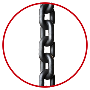
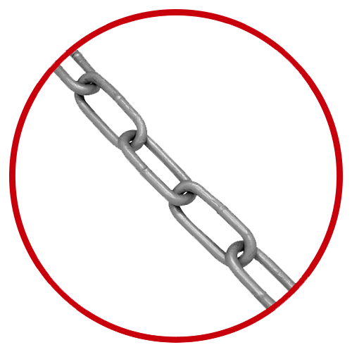
Chaînes de convoyage agricoles pour transmission A550 A555 A557 A620 Ca627 Ca550d Ca555D Ca557D (vente populaire)
Chaînes de convoyage agricoles pour transmission A550 A555 A557 A620 Ca627 Ca550d Ca555D Ca557D (vente populaire)
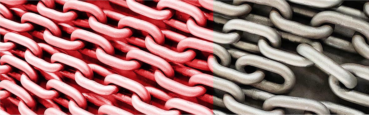
Catégorie
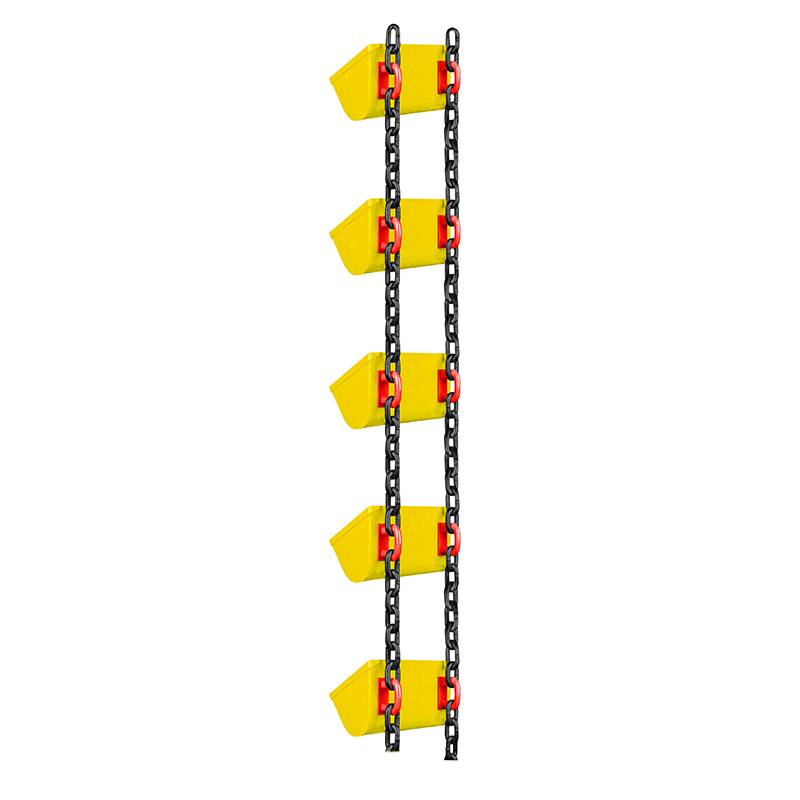
Application
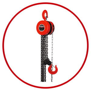
Produits associés

Paramètre de chaîne
Figure 1 : Dimensions des chaînes à maillons ronds en acier DIN 764 et DIN 766
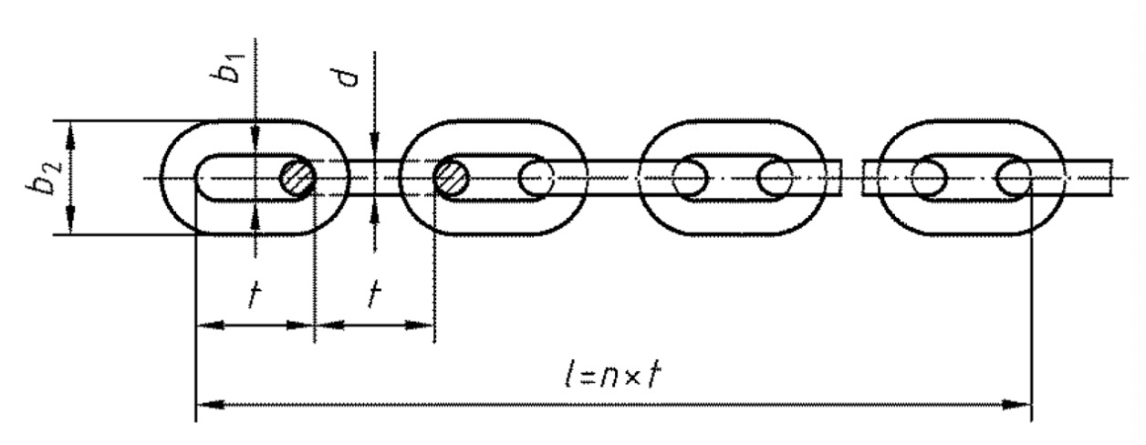
Tableau 1 : Dimensions (mm) de la chaîne à maillons ronds en acier DIN 764 (G30 et G50)
| nominal | diamètre | pas | largeur | longueur de jauge (11 maillons) | kg/m | |||||
| dxt | d | tolérance | t | tolérance | intérieur | extérieur | l | tolérance | ||
| classe A | classe B | |||||||||
| 10 x 35 | 10 | ± 0,4 | 35 | +0,6/-0,2 | 14.0 | 36 | 385 | +2/-1 | +3/-1 | 2.1 |
| 13 x 45 | 13 | ± 0,5 | 45 | +0,8/-0,3 | 18.0 | 47 | 495 | +3/-1 | +4/-1 | 3.5 |
| 16 x 56 | 16 | ± 0,6 | 56 | +1,0/-0,3 | 22.0 | 58 | 616 | +3/-1 | +5/-2 | 5.3 |
| 18 x 63 | 18 | ± 0,9 | 63 | +1,1/-0,4 | 24.0 | 65 | 693 | +4/-1 | +6/-2 | 6.7 |
| 20 x 70 | 20 | ± 1,0 | 70 | +1,3/-0,4 | 27.0 | 72 | 770 | +4/-1 | +6/-2 | 8.3 |
| 23 x 80 | 23 | ± 1,2 | 80 | +1,4/-0,5 | 31.0 | 83 | 880 | +5/-2 | +7/-2 | 11.0 |
| 26 x 91 | 26 | ± 1,3 | 91 | +1,6/-0,5 | 35.0 | 94 | 1001 | +5/-2 | +8/-3 | 14.0 |
| 30 x 105 | 30 | ± 1,5 | 105 | +1,9/-0,6 | 39.0 | 108 | 1155 | +6/-2 | +9/-3 | 18,5 |
| 33 x 115 | 33 | ± 1,7 | 115 | +2,1/-0,7 | 43.0 | 119 | 1265 | +7/-2 | +10/-3 | 22,5 |
| 36 x 126 | 36 | ± 1,8 | 126 | +2,3/-0,8 | 47.0 | 130 | 1386 | +7/-2 | +11/-4 | 27.0 |
| 39 x 136 | 39 | ± 2,0 | 136 | +2,4/-0,8 | 51.0 | 140 | 1496 | +8/-3 | +12/-4 | 31,5 |
| 42 x 147 | 42 | ± 2,1 | 147 | +2,6/-0,9 | 55.0 | 151 | 1617 | +9/-3 | +13/-4 | 36,5 |
Tableau 2 : Dimensions des chaînes à maillons ronds en acier DIN 766 (mm)
| nominal | diamètre | pas | largeur | longueur de jauge (11 maillons) | kg/m | |||||
| dxt | d | tolérance | t | tolérance | intérieur | extérieur | l | tolérance | ||
| classe A | classe B | |||||||||
| 10 x 28 | 10 | ± 0,4 | 28 | +0,5/-0,3 | 14.0 | 36 | 308 | +2 /-1 | +2 /-1 | 2.3 |
| 13 x 36 | 13 | ± 0,5 | 36 | +0,6/-0,3 | 18.0 | 47 | 396 | +2 /-1 | +3 /-2 | 3.9 |
| 16 x 45 | 16 | ± 0,6 | 45 | +0,8/-0,4 | 22,5 | 58 | 496 | +3 /-1 | +4 /-2 | 5.9 |
| 18 x 50 | 18 | ± 0,9 | 50 | +0,9/-0,5 | 25.0 | 65 | 550 | +3 /-1 | +4 /-2 | 7,5 |
| 20 x 56 | 20 | ± 1,0 | 56 | +1,0/-0,5 | 28.0 | 72 | 616 | +3 /-2 | +5 /-2 | 9.2 |
| 23 x 64 | 23 | ± 1,2 | 64 | +1,2/-0,6 | 32.0 | 83 | 704 | +4 /-2 | +6 /-3 | 12.0 |
| 26 x 73 | 26 | ± 1,3 | 73 | +1,3/-0,7 | 34.0 | 94 | 803 | +4 /-2 | +6 /-3 | 15,5 |
| 30 x 84 | 30 | ± 1,5 | 84 | +1,5/-0,8 | 39.0 | 108 | 924 | +5 /-2 | +7 /-4 | 20,5 |
| 33 x 92 | 33 | ± 1,7 | 92 | +1,7/-0,8 | 43.0 | 119 | 1012 | +5 /-3 | +8 /-4 | 25.0 |
| 36 x 101 | 36 | ± 1,8 | 101 | +1,8/-0,9 | 47.0 | 130 | 1111 | +6 /-3 | +9 /-4 | 29,5 |
| 39 x 109 | 39 | ± 2,0 | 109 | +2,0/-1,0 | 50,5 | 140 | 1199 | +6 /-3 | +10 /-5 | 35.0 |
| 42 x 118 | 42 | ± 2,1 | 118 | +2,1/-1,1 | 54,5 | 151 | 1298 | +7 /-4 | +10 /-5 | 40,5 |
Tableau 3 : Force de travail et propriétés mécaniques de la chaîne à maillons ronds en acier DIN 764 (G30 et G50)
| taille nominale | main-d'œuvre | fabrication | force de freinage | déflexion de flexion | allongement total ultime | |||||
| G30 | G50 | G30 | G50 | G30 | G50 | G30 | G50 | G30 | G50 | |
| 10 x 35 | 12,5 | 20 | 36 | 56 | 50 | 80 | 10 | 10 | 20 | 15 |
| 13 x 45 | 20 | 32 | 56 | 90 | 80 | 125 | 13 | 13 | ||
| 16 x 56 | 32 | 50 | 90 | 140 | 125 | 200 | 16 | 16 | ||
| 18 x 63 | 40 | 63 | 110 | 180 | 160 | 250 | 18 | 18 | ||
| 20 x 70 | 50 | 80 | 140 | 220 | 200 | 320 | 20 | 20 | ||
| 23 x 80 | 63 | 100 | 180 | 280 | 250 | 400 | 23 | 23 | ||
| 26 x 91 | 80 | 125 | 220 | 360 | 320 | 500 | 26 | 26 | ||
| 30 x 105 | 110 | 180 | 320 | 500 | 450 | 710 | 30 | 30 | ||
| 33 x 115 | 125 | 200 | 360 | 560 | 500 | 800 | 33 | 33 | ||
| 36 x 126 | 160 | 250 | 450 | 710 | 630 | 1000 | 36 | 36 | ||
| 39 x 136 | 180 | 280 | 500 | 800 | 710 | 1100 | 39 | 39 | ||
| 42 x 147 | 220 | 360 | 630 | 1000 | 900 | 1400 | 42 | 42 | ||
Tableau 4 : Force de travail et propriétés mécaniques d’une chaîne à maillons ronds en acier DIN 766
| taille nominale
| main-d'œuvre | fabrication | force de freinage | déflexion de flexion | allongement total ultime | |
| verticale | horizontal | |||||
| 10 x 28 | 10 | 12,5 | 36 | 50 | 8 | 20 |
| 13 x 36 | 16 | 20 | 56 | 80 | 10 | |
| 16 x 45 | 25 | 32 | 90 | 125 | 13 | |
| 18 x 50 | 32 | 40 | 110 | 160 | 14 | |
| 20 x 56 | 40 | 50 | 140 | 200 | 16 | |
| 23 x 64 | 50 | 63 | 180 | 250 | 18 | |
| 26 x 73 | 63 | 80 | 220 | 320 | 21 | |
| 30 x 84 | 90 | 110 | 320 | 450 | 24 | |
| 33 x 92 | 110 | 130 | 380 | 530 | 26 | |
| 36 x 101 | 125 | 160 | 450 | 630 | 29 | |
| 39 x 109 | 150 | 190 | 530 | 750 | 31 | |
| 42 x 118 | 180 | 220 | 630 | 900 | 34 | |
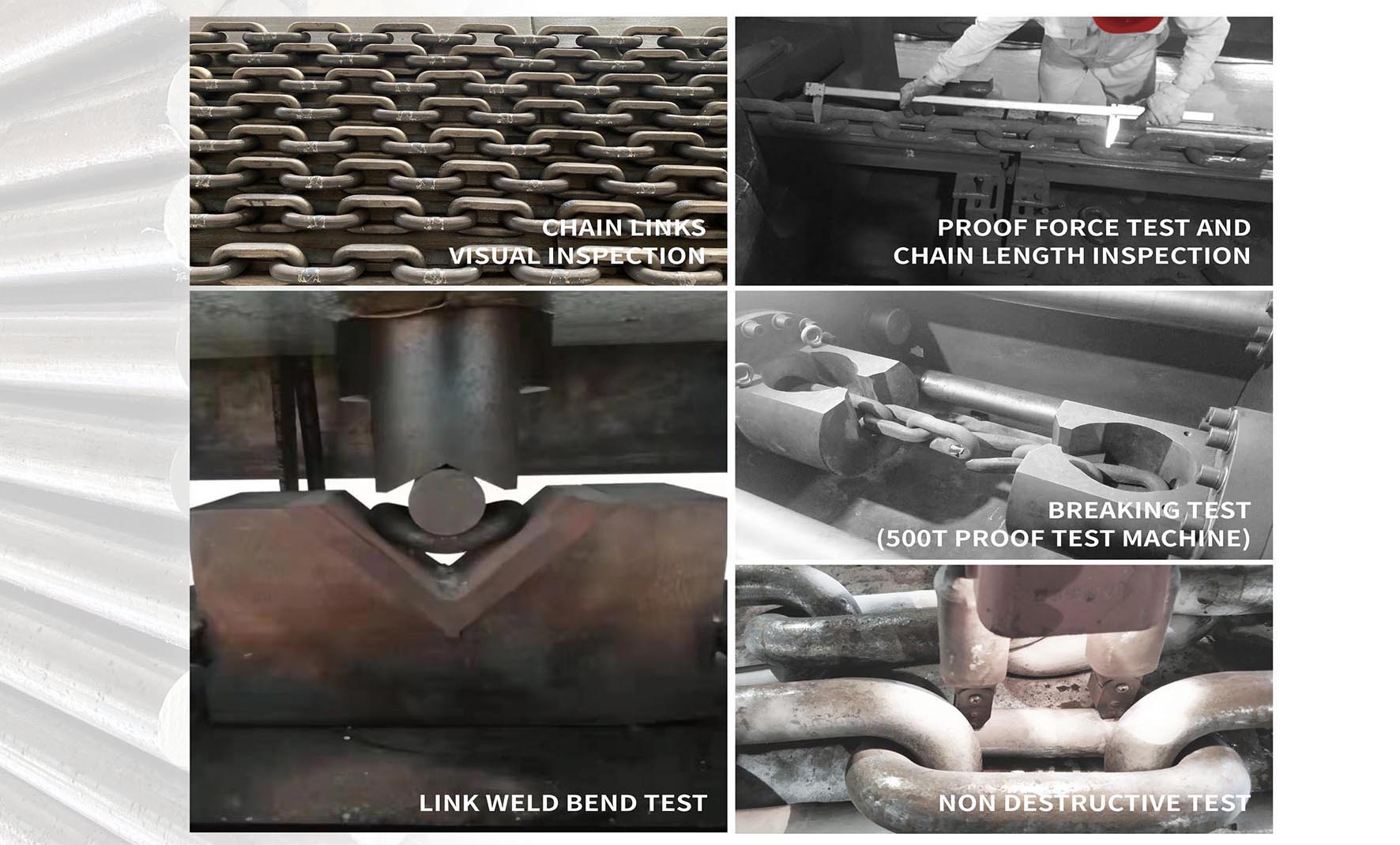
Inspection du site
Notre service